Lo-Fi Delay/Filter Effect
One of the first synths I really fell in love with was the Korg Monotron Delay. Korg was kind enough to make the schematics available for the DIY community, and over the years a lot of cool mods have been documented online. There are instructions online on rehousing the Delay into the form of a eurorack module. I was always intrigued by the idea of a Monotron Delay in my modular synth, but there are a couple of drawbacks. First, I only want it to process audio, so the onboard oscillator is kinda wasted. That also makes the onboard VCA and LFO unnecessary too. There’s no way to control the delay time and feedback with CV. And lastly, it runs on 5V, so it’s not suited to eurorack audio.
I decided to use Korg’s schematics as a jumping off point, but ultimately the goal was to design my own take on the idea. The effect section of the Monotron Delay consists of a PT2399 delay with an MS-20 lowpass filter inside the feedback loop - that will be the starting point.
PT2399 Delay
The PT2399 is an IC designed to provide reverb in cheap karaoke microphones. It’s a digital delay, but it doesn’t require any external RAM or crystals or any of the other things that microprocessors usually need. That’s all built into the IC. And even though it has a digital core, it’s controlled with CV and convincingly sounds analog thanks to a tape delay style response where changing the delay time also changes the pitch of the audio. Also you can get them on Tayda for under a dollar.
Skull & Circuits posted schematics for his take on a PT2399 delay for eurorack, and provided a great write up as well. His design includes cv control over feedback and delay time. I only had to tweak it a little bit to suit my needs, and it sounds great. Here is the core of the delay circuit, it is pretty much taken directly from the chip’s datasheet.

The big change from the datasheet is pin 6, which sets the delay time. They show a variable resistor to ground, but in order to implement voltage control it will need to be more complicated. S&C uses a variation on a long tailed pair to achieve this. I had to tweak some resistor values to make it work, here is what I ended up with:

Everything to the left of Q1 is summing and offsetting voltages from the control pot and CV input, and scaling the output down to the range usable by a transistor’s base pin. On the right is an exponential voltage to current converter. If you want to learn more about that (it’s a concept I still don’t fully grok to be honest), North Coast Synthesis covers the topic extensively and Rene Schimtz does as well. It’s necessary in this case because the PT2399’s delay time is current controlled, not voltage controlled.
That takes care of CV over delay time; now we need to focus on feedback. But before I talk about that, I want to take a step back and talk about how feedback fits in the context of this circuit.
The PT2399 really has just a single, simple function. All it does is take an incoming signal, wait about a second, and then spit out a copy. The way you get an echo effect is to mix the output back into the input for repeating echoes. You control the number of echoes by controlling the amplitude of the feedback path. And since I want it to be voltage controlled, that means we will need to implement a VCA.

Skull & Circuits use a vactrol here. At first I thought that was a hacky, temporary solution, but after considering the alternatives I think it makes a lot of sense. Using a discrete transistor VCA requires calibration or else the signal will get distorted, and you need a nice steady wave to perform the calibration, which would be tricky to implement in the middle of a delay effect. Another option is a dedicated VCA IC like the SSI2164 or AS3360, but that feels like a waste since they contain multiple VCAs and this circuit only calls for one. Also those chips are like $5 each.
Vactrols on the other hand are cheap and easy to implement. And while they have flaws, such as inconsistency from one unit to the next, those don’t cause problems in this case. We aren’t looking for a VCA that responds perfectly to CV from 0 to 5V here - we just need the audio to generally get quieter or louder, and precision isn’t super important.
Now that the feedback path is set up, we just need to add a simple mixer so the feedback can be mixed with the input. Putting all that together, here is what we get:

Now on to the filter. Don’t tell anyone but I’m not a huge fan of the MS-20 filter. And since the PT2399 has a sound characterized as “gritty” or “lo-fi”, I thought it would be cool to pair it with a clean, smooth sounding filter. The 2164 family of ICs can be used for that kind of sound, and in addition it is possible to get a huge range of modes out of it via pole mixing. I dropped an AS2164 based filter inside the feedback path, and loved the result.
AS2164 Multimode Filter
There are a ton of great resources for building filters around the 2164 (sidenote: there are a couple of different versions of this IC made by different companies, but they are all mostly interchangeable. SSM2164, AS2164, and V2164 are all through hole while SSI2164 is SMD. I use AS2164 in my projects). The first resource to check is always the datasheet. According to this one, you can use the 2164 to make VCAs, VCOs, LFOs, mixers - you can almost make a whole synth from this chip. But in order to design a filter, they refer you to a separate 32-page document: AN701 Designing Voltage Controlled Filters for Synthesizers with the SSI2164. This thing is a goldmine.
On page 19, they introduce the concept of “pole mixing.” The idea is that in a four pole filter, you can mix the output of each pole in specific ratios to achieve different responses: high pass, band pass, notch, and so on. You can also get different cutoff slopes for each mode, such as one pole, two pole, asymmetric band pass… all kinds of options. That is going to be super important for the module I’m designing, as I want it to have a really flexible filter.
To get there, we need to start with the standard 2164 filter circuit. Below is one low pass stage, similar to the one shown in AN701 but using resistor and capacitor values used in Mutable Instruments Ripples.

We’ll put four of these together in series to get a four pole filter.

And finally, mix the output back into the input to get resonance.

And that’s the core of the filter circuit! I wouldn’t normally set up a mixer in the way shown above, but that is how they do it in the datasheet and it works. If you wanted to have CV control over resonance, you would need to replace the circuit around U3B and U3C with a VCA. That’s not a feature I’m looking to include, so a simple attenuator will do.
The cutoff CV is a little complicated to set up. In this circuit, when the cutoff CV is 0V the filter is open, and when cutoff CV is 3V the filter is closed. That’s the opposite of what an end user would expect, which means we will need to alter the signals coming from the pot and CV input. The pot will need to be wired backwards, and the CV will need to be inverted and scaled down a little. Here is the solution I came up with:

The cutoff pot is wired backwards, with pin 1 connected to +5V and pin 3 to ground. The CV attenuator is wired the usual way, but the output is subtracted from the cutoff pot’s voltage instead of added to it. In this configuration, the pot and CV input behave in the way a user would expect.
Now that the filter is up and running, we can move on to the pole mixing. I want this filter to be flexible, so I decided to include low pass, band pass, and high pass, each with the option of one pole or two poles. I avoided four pole outputs because this filter is going to be inside the delay’s feedback loop, and I want the filter to change the sound a little bit with every echo. A four pole filter would remove too many harmonics at once and then not have much effect on subsequent echoes. A one or two pole filter can keep changing the sound with each echo.
With that in mind, lets look at the specifics of pole mixing. The idea is that you mix the output of each filter stage and the filter input in specific ratios to get specific filter modes. This is illustrated in figure 35 of AN701.
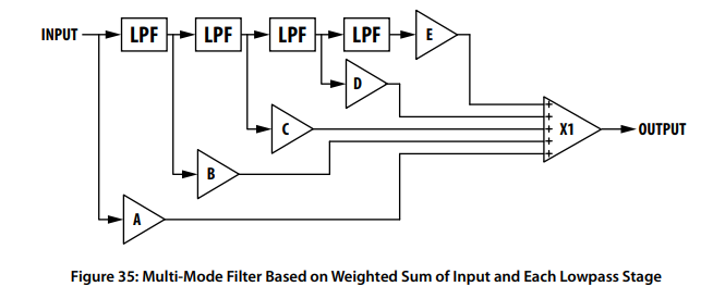
The convenient thing here is that each filter stage inverts the signal, which makes it easy to subtract one signal from another. Subtraction is the key to make pole mixing work. For example, if you take the input signal (A in the diagram above) and subtract the one pole low pass signal (B above), you are left with a one pole high pass filter. Electric Druid has some nice illustrations of this in his write up on this topic.
Below is the pole mixing ratios we will use to get the desired outputs:
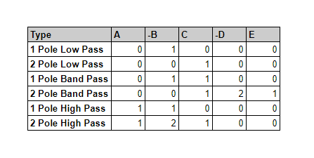
The low pass ones are easy, they can just be tapped directly from the filter core. The others require a mixer, and end up looking like this:
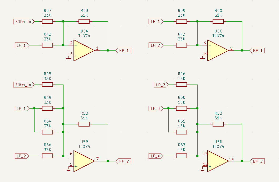
Resistor values were chosen by ear. The important thing is that each mixer’s inputs use the same value resistors, to ensure we get the correct ratios for pole mixing.
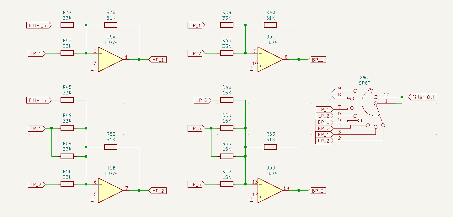
If this were a standalone filter module, we could have individual outputs for each filter mode. But because this filter is inside a delay’s feedback loop, we will need to build in a switch to select which mode is active. I will use a rotary six-position switch.
Now it is time to put everything together.
Combining Delay and Filter
After trying it out both ways, I decided to put the filter before the delay. Otherwise, the first echo that comes out of the 2399 is unfiltered. If the filter is first, everything sounds more cohesive. So the signal path will be:

So we’ll need a mixer on the input to mix in the feedback signal, and a crossfader on the output to blend between wet and dry. We also need to attenuate the input since the PT2399 only accepts 0-5V, and then amplify the output back up to eurorack levels. After some testing I decided attenuating the input to 1/3 of the original amplitude works well. So here is the input attenuator/mixer:

R3 and R6 make a voltage divider that brings the input down to 1/3 its original amplitude. U1A is a buffer and its output is used as the Dry signal in the Dry/Wet mix. The dry input is mixed with the PT2399’s output before going to the filter input. The filter’s output mode is selected with the rotary switch, and then routed to the delay input. The delay output is then routed to two places: one goes through the vactrol VCA and is mixed with the input, and the other is used as the Wet signal in the Wet/Dry mix.

The circuit around RV8 is a crossfader. It converts R61 and R67 into parallel voltage dividers that work in opposite directions, so that as one gets quieter the other gets louder. However, due to the setup of the voltage dividers, both signals end up attenuated. Normally the feedback resistor (R64) would be 51K to boost the output back up to the original level. But remember, the input signal’s amplitude was dropped down to 1/3 to accommodate the PT2399’s 0-5V range. So the output amplitude needs to be tripled to get it back up to eurorack levels. As a result, a 150K resistor is used for R64.
The output audio is also routed through an LED for visual feedback. The LED is isolated from the rest of the circuit by Q3, so it doesn’t affect the audio.
So the module is in a working state! I played around with it and loved the sound. I did quickly notice the need for just a couple of changes and extra features.
The first adjustment is to the resonance level. Since resonance is a positive feedback loop, when you place it inside the delay’s feedback loop it quickly gets out of control. I had to tamp down the resonance, and I did that by increasing R35 from 10K to 100K. That reduces the filter output relative to the filter input in the resonance mix.

On the other hand, I felt that the delay feedback often needed to be increased above its input level. The filter removes a lot of harmonics, which causes it to sound quieter. I decided that the feedback ought to be able to amplify the delay’s output in addition to attenuating it, so I added a “Boost” switch.

When the feedback is routed through R8, it tops out at 100% of the delay’s input. When it is routed through R7, it tops out at 150%. That extra 50% goes a long way to filling out the sound. If you crank up both the feedback and the resonance the module basically turns into a Karplus-Strong machine, which can be a lot of fun. But I want it to be able to do other things, too. If you’re interested in modding this circuit, try lower value resistors for R7 and see how wild it can get.
There’s one last change I want to implement. In the Wet/Dry mix, the wet is processed by both the filter and the delay while the dry is processed by neither. I wanted to figure out a way to run the dry signal through the filter, for a more cohesive sound. Unfortunately, the filter is inside the delay’s feedback loop, so if you tap the filter’s output there is no way to remove the echoes. The compromise I came up with is to add another switch, called “Filter Dry.”

When the switch is down, the dry signal is taken from the input, and is truly dry. You can bypass the effect by turning Wet/Dry all the way to the dry side in this configuration. When the switch is up, the dry signal is taken from the filter’s output. In this mode, all of the sound at the output has been passed through the filter, but you cannot isolate the input signal. The Wet/Dry knob blends from the AS2164’s output to the PT2399’s output. Those two signals do have some sonic differences - the AS2164 is clean and smooth sounding, while the PT2399 is lofi and crunchy. But in that switch position, the Wet/Dry knob can’t actually produce a dry signal.
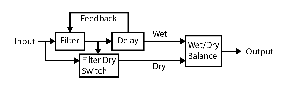
And that’s the whole module! The complete signal path is shown above.
I might continue tweaking this circuit in the future. It took a long time for me to get all the pieces working, so once it was in a good state I didn’t want to mess with it further. But maybe in a little while I will come back to it. There are some buffers and mix stages that I think might be redundant - I started working on removing them from the schematics to reduce the number of op amps needed, but it turns out that TL074s are cheaper than TL072s. So I would need to remove 4 op amps , and it would save me a whopping 59 cents. I decided that since the module works, it wasn’t worth the time to mess with the circuit and try to make it more efficient.
The other thing I want to look into is the high pass filter response. For some reason, whenever resonance is set to a nonzero amount, low frequencies bleed though. I want to test out the filter circuit in isolation and see if that is normal behavior or not.
But for now, the module works and in my opinion it sounds really really good!